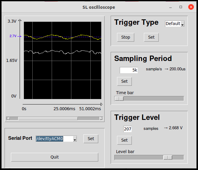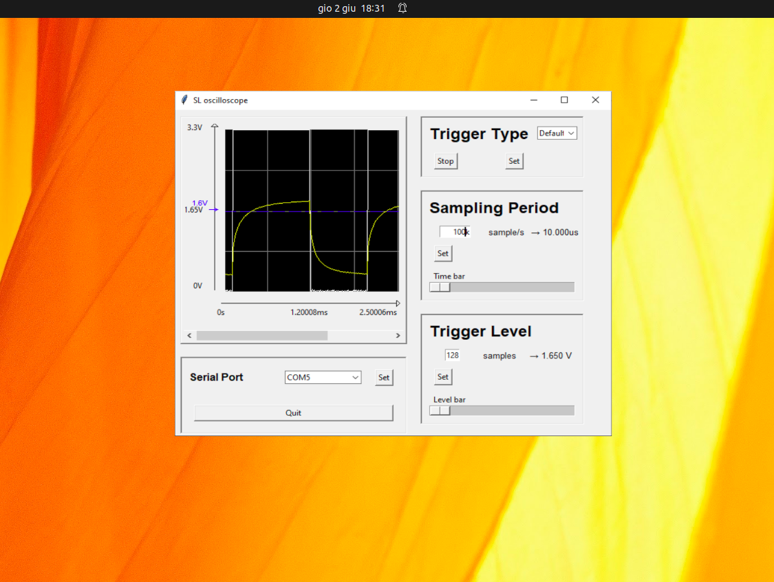
It can work out of the box with a STM32F401RE board by flashing on it the content of the STM_CUBE_BUILD directory as shown in the following. Anyway it is shown how to use it on every board compatible with the STM32CubeIDE.
Input channels: 2
Input voltage range: 0V – 3,3V
Resolution: 256 levels
Sample frequency: 10Hz – 100kHz
Trigger types: Auto / Normal / Single / Stop
Trigger levels [V]: 0V – 3,3V
Display resolution: 256 x 256 points
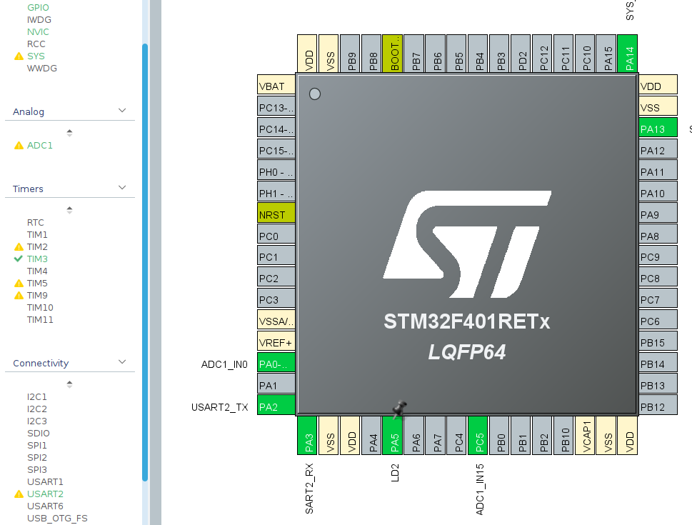
By default, the pins used for the acquisition of the signals are:
•CH1: PA0
•CH2: PC5
Voltage samples are taken from the card which via serial communication transmits the signal to the PC, via USB interface, to be displayed.
For the graphical realization of the UI the library tkinter was used.
In order to open the UI at least a serial device must be connected when the software is executed.
If more then one serial device is connected, it must be choosed the correct device as follow:
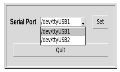
It is possible to change the trigger:
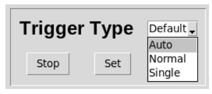
at initialization you have “Default” in the check box, this option is not present in the box and therefore it is not possible to select it once you have chosen another type of trigger.
Change the sampling period:
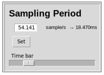
It offers the ability to set the sampling frequency, the time between an ADC acquisition and the next one.
At initialization, when the trigger type selected is “Default”, this parameter is set to 1kHz or 1ms.
As from specification, the maximum range are 10 Hz - 100 kHz.
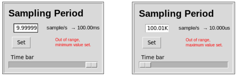
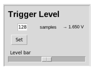
Change the trigger level:
Can be choosen between 0 and 256, corresponding to 0V and 3.3V.
Observation:
It is always preferred if you use the input box instead of the bar since in this way the board can set exactly the value you want directly, without setting value after value the ones that scrolls the mouse bar.
The main features of this device are:
•clock frequency up to 84 MHz
•512 Kbytes of Flash memory
•96 Kbytes of SRAM
To use this project out of the shelf it is needed to download the STM32CubeIDE SW.
Open the IDE and choose File -> Import Projects from File System then select the content of the directory STM_CUBE_BUILD (Oscilloscope_II) as source.
Click on finish then the project can be buid and run on the board.
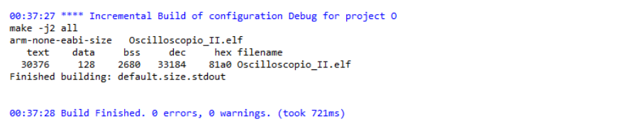
On a different board It is needed to choose exactly the same configurations in the Cube tool in order to reduce the efford to use the code.
Any obliged changes can be adjusted after.
Open File -> new -> STM32 project then select your board.
Now it is necessary to select the following settings:
Setup the ADC
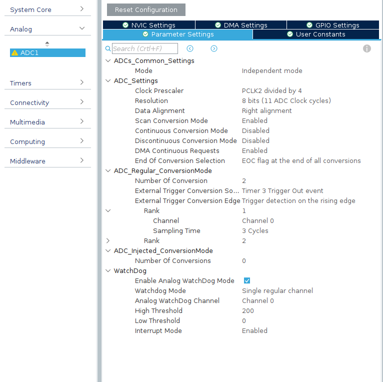
The F401RE board has a multi-channel ADC, in this project channels 0 and 15 have been enabled, respectively as channel 1 (Rank 1) and channel 2 (Rank 2), to minimize possible cross-talk.
Try to select the same options.
Scan Conversion has been set as acquisition mode in order to perform a sampling of the two channels belonging to the “Regular group” of an event.
The triggering event is generated by the update event of the timer 3.
It is also set the continuous request to the DMA for efficient transfer of samples, in as regular channels all share the same register and need to be transferred quickly.
To identify the trigger level it is used the analog watchdog in which the task is to check when, compared to channel 1, the input signal is above a certain threshold, so that unleash an interrupt.
Finally, having a resolution of 8 bits, note that the sampling time is defined as:
3Cycles + 8bit = 11 ADCCLK cycles
Being the ADC clock PCLK2/4 we get about 0.5 μs
Setup the TIM3
Timer 3 channel 1 in output compare no output mode to define the sampling frequency.
When the value set in the 16-bit Auto Reload Register is reached it is triggered an interrupt corresponding to the Update Event Flag setting.
This value is dynamically set within the design to sample at the frequency requested by the user.
The prescaler can also be set for the same reason according to the formula:
fsample = 84 ∙ 106 /( (PSC + 1) (ARR + 1) )
The Update event is therefore used as a trigger to start channel conversions regular.
Setup the DMA
The DMA (Direct Memory Access) has been set up in circular mode, so that when the portion of memory dedicated to the acquisition of the samples can be filled again, exploiting a conceptually FIFO type access.
Setup the USART
The USART protocol used by the card has been set to the maximum baud rate, corresponding to 115 200 Bit/s.
As the reception is asynchronous, an oversampling factor x16 is set.
Different hardware
To match different obliged choices in the setup it is necessary to look at the functions in the file main.c named as MX__INIT and compensate for the mismatch.
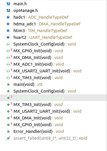
It could be necessary also to set up the HW related values declared as #define, in the files under the src directory, and the HW used in the CallBack declaration file.
Then the project can be buid and run on the board.
To execute the software simply launch the executable in the main directory, one for Windows and one for Unix.
Pay attention that the board must be connected in order to open the visual interface.